
GT-VX1 Assembly Documentation
The sample files below show the level of detail in our 2D documentation. All kits are also provided with 3D pdf models. (3D models are currently not available on-line)
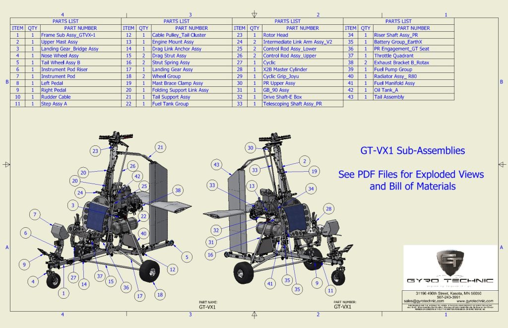
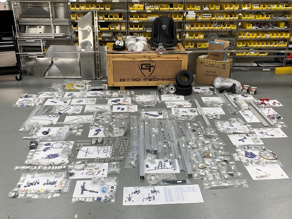
Files below correspond to the item number of the sub assemblies shown in picture above.
2D PDF Drawings
- 1 – Frame Sub Assy GT-VX1
- 2 – Upper Mast Assy
- 3 – Landing Gear_Bridge Assy
- 4 – Nose Wheel Assy
- 5 – Tail Wheel Assy B
- 6 – Inst Pod Riser
- 7 – Instrument Pod
- 8 – Left Pedal
- 9 – Right Pedal
- 10 – Rudder Cable Assy
- 11 – Step Assy A
- 12 – Cable Pulley_Tail Cluster
- 13 – Engine Mount Assy
- 14 – Drag Link Anchor Assy
- 15 – Drag Link Assy
- 16 – Strut Spring Assy
- 17 – Landing Gear Assy
- 18 – Wheel Group
- 19 – Mast Brace Clamp Assy
- 20 – Folding Support Link Assy
- 21 – Tail Support Assy
- 22 – Fuel Tank Group
- 23 – Rotor Head
- 24 – Intermediate Link Assy
- 25 – Control Rod Assy_Lower
- 26 – Control Rod Assy_Upper
- 27 – Cyclic
- 28 – X2B Master Cylinder
- 29 – Grip Assy_Cyclic
- 30 – PR Upper Assy
- 31 – GB_90 Assy
- 32 – Drive Shaft – E Box
- 33 – Telescoping Shaft Assy_PR
- 34 – Riser Shaft Assy_PR
- 35 – Battery Group
- 36 – PR Engagement
- 37 – Throttle Quadrant
- 38 – Exhaust Bracket B_Rotax
- 39 – Fuel Pump Group
- 40 – Radiator Assy_R80
- 41 – Fuel Manifold Assy
- 42 – Oil Tank_A
- 43 – Tail Assy
